
Integrated Security Systems: Control Rooms, Cause-and-Effect, Commissioning and Lifecycle Management
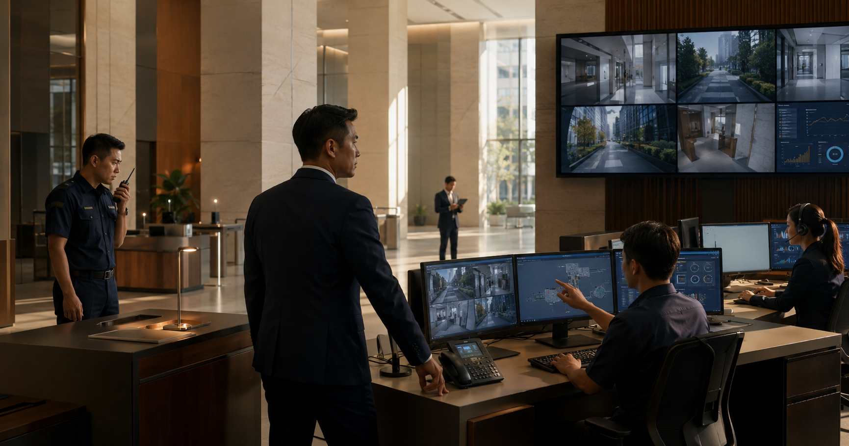
A building can have an excellent CCTV system, a reliable access-control system and a well-designed intrusion alarm system and still have a poor security operation.
The reason is simple:
Individual systems can work correctly while the interfaces between them fail.
A door alarm may appear in the access-control software but the operator has to search manually for the associated camera.
An intrusion alarm may be technically correct but appear with such a low priority that it sits unnoticed among hundreds of routine events.
A panic button may activate an alarm but nobody has defined:
who receives it, what cameras appear, what the operator should do or how the event is escalated.
Good integrated security engineering therefore goes beyond connecting systems together.
It defines:
Event → Information → Verification → Decision → Response
This guide focuses on that integration layer: how security systems should interact, how cause-and-effect logic is developed, how the Security Control Room should support operators, and how the entire system is tested and maintained throughout its lifecycle.
The SPF VSS Standard recognises the operational value of integration, giving the example of a security alarm notifying an officer, showing the alarm location on a site plan and presenting the relevant camera for verification.
The engineering question is:
How do we turn that principle into a complete operating system?
- Start with the security operation, not the software platform
A common integration approach is:
“We have CCTV brand X and access control brand Y. Can we integrate them?”
That is a technology question.
The better first question is:
What should happen when a security event occurs?
For example:
Event
Server-room door opens without authorised access.
Desired security outcome
- Generate high-priority alarm.
- Identify exact door and location.
- Automatically display relevant camera.
- Show recent associated access events.
- Operator verifies event.
- Operator follows response procedure.
- Incident is recorded and retained for investigation.
Only after defining that workflow do we determine:
which platforms and interfaces are required to deliver it.
- Integration is more than putting everything on one screen
A single graphical interface can be useful.
But:
one screen does not automatically mean one integrated system.
True operational integration means information from different systems is used together to improve:
detection, verification, decision-making and response.
For example:
Access control reports:
Door Forced – L12 Server Room
CCTV provides:
CAM-L12-SVR-01
Building plan provides:
Location highlighted
Security procedure provides:
Response instruction
The operator receives one coherent event rather than four unrelated systems.
- Systems commonly involved in physical-security integration
Depending on the facility, an integrated security environment may include:
- Video Surveillance System;
- Access Control System;
- Intrusion Detection System;
- intercom / video intercom;
- panic or duress alarms;
- visitor management;
- turnstiles and speed gates;
- perimeter detection;
- vehicle access systems;
- building-management interfaces;
- fire-alarm status where relevant to security operation;
- lift interfaces;
- key-management systems;
- security communication systems;
- remote monitoring platforms.
Not every project needs all of them.
Integration should follow the operational requirement rather than a desire to connect everything simply because an API exists.
- Identify the system of record for each function
When systems are integrated, it should remain clear which system is authoritative for each type of data.
For example:
Information | Possible System of Record |
|---|---|
Employee access rights | Access Control System |
Camera video | VMS |
Visitor record | Visitor Management System |
Intrusion event | IDS / ACS depending on design |
Operator incident record | Incident-management platform |
Door status | Access Control System |
Video evidence | VMS/NVR |
This avoids a common problem:
The same information exists in several systems, but nobody knows which one is authoritative.
- Avoid unnecessary duplication of databases
Suppose access-control users are copied into:
ACS, visitor software, monitoring software and an integration platform.
If each system maintains its own independent data, updates can become inconsistent.
Where practical, integration should minimise duplicated administration.
For example:
ACS remains authoritative for cardholder access.
The integrated platform consumes only the data it actually needs.
The precise architecture depends on vendor capability and cybersecurity requirements.
- Define events before defining integrations
Start with an event register.
Typical events might include:
Access Control
- valid access;
- access denied;
- door forced;
- door held;
- controller offline;
- reader offline;
- emergency release;
- cabinet tamper;
- power fault.
Intrusion Detection
- perimeter intrusion;
- motion alarm;
- glass-break alarm;
- enclosure tamper;
- zone fault;
- communication failure.
CCTV
- camera offline;
- video loss;
- analytic tripwire;
- loitering;
- recorder fault;
- storage fault.
Intercom
- call initiated;
- call unanswered;
- door release requested.
Duress
- panic alarm;
- silent duress;
- emergency assistance request.
Each event should then be evaluated:
Does security need to know about this?
How urgently?
What other information helps verify it?
What action follows?
- Not every event should become an operator alarm
This is critical.
A security platform may generate thousands of technical events.
If every one appears as:
URGENT SECURITY ALARM
the system quickly becomes unusable.
Events should generally be separated into categories such as:
Security alarm
Operational warning
Technical fault
Routine transaction
Audit/log event
For example:
Valid Access
usually needs to be logged.
It may not require operator acknowledgement.
Door Forced at Critical Room
may require immediate operator attention.
Camera firmware update available
belongs to maintenance rather than immediate incident response.
- Alarm priority should reflect consequence
A useful priority structure could be:
Priority | Typical Meaning | Example |
|---|---|---|
P1 Critical | Immediate threat / emergency | Duress, confirmed intrusion into Critical Area |
P2 High | Serious security event requiring rapid verification | Door forced, perimeter breach |
P3 Medium | Security anomaly requiring attention | Door held, repeated invalid access |
P4 Technical | Equipment or infrastructure issue | Camera offline, disk fault |
P5 Information | Event logged for reference | Valid access |
This is an example framework, not a universal classification.
Each organisation should define priorities according to its risks and response capability.
- Alarm priority should also affect presentation
A critical alarm should not look identical to an informational event.
Depending on the platform, priority may influence:
- audible alert;
- screen prominence;
- pop-up behaviour;
- acknowledgement requirements;
- escalation timer;
- notification recipients;
- event colour or icon;
- automatic camera display.
The goal is:
help the operator identify what matters first.
- Build a Cause-and-Effect Matrix
A Cause-and-Effect Matrix is one of the most useful documents in integrated security engineering.
It defines:
When this occurs, what should the system do?
A simplified example:
Cause | System Action | CCTV Action | Operator Action |
|---|---|---|---|
Valid card | Unlock door | None / optional bookmark | None |
Invalid card | Keep secure | Optional associated view | Log / assess if repeated |
Door Forced | High-priority alarm | Pop associated camera | Verify and respond |
Door Held | Alarm after delay | Pop associated camera | Determine cause |
Perimeter intrusion | Intrusion alarm | Display nearest cameras | Verify and dispatch |
Duress | Critical alarm | Display relevant cameras | Follow emergency SOP |
Camera offline | Technical alarm | N/A | Escalate maintenance |
Fire condition | Execute approved door behaviour | Optional status display | Follow approved procedure |
The exact matrix is project-specific.
Its value is that everybody agrees on system behaviour before programming begins.
- Cause-and-effect should be agreed before commissioning
If the matrix is created only during SAT, it is too late.
By then:
the software may already be configured, interfaces built and operator workflows assumed.
Cause-and-effect should be developed during detailed design with input from:
- security management;
- security consultant/designer;
- integrator;
- facilities;
- IT;
- fire/life-safety stakeholders where relevant;
- end users / operators.
Commissioning then proves the approved logic.
- Separate automatic system actions from human decisions
This is important.
Some actions are appropriate for automation.
For example:
Door Forced → display camera.
Others may require human judgement.
For example:
Camera shows unknown person → determine whether response is required.
Do not automatically turn:
Detection
into:
Physical security action
without considering the consequences.
For example, automatically locking or unlocking unrelated doors based on an analytic event may create operational or life-safety problems if poorly designed.
- A useful integrated event sequence
A strong design often follows:
Detect
↓
Notify
↓
Locate
↓
Present relevant information
↓
Verify
↓
Decide
↓
Respond
↓
Record
This is more meaningful than simply:
Alarm generated.
- Example: Door Forced
Consider a high-security equipment room.
Cause
Door contact opens.
No valid access event exists.
Access Control
Generate:
Door Forced – Equipment Room
Integrated platform
Assign:
High Priority
CCTV
Automatically display:
camera covering the doorway
and possibly:
nearby approach camera.
Operator
Verifies:
person, activity and direction of movement.
Response
Follow agreed escalation:
security officer dispatch, supervisor notification or other approved action.
Evidence
Bookmark or correlate:
access event + associated video + operator actions.
Now the systems are supporting one security outcome.
- Example: Door Held Open
The workflow may be different.
Cause
Valid access occurred.
Door remained open beyond the authorised time.
System
Generate:
Door Held – Staff Entrance
CCTV
Display entrance camera.
Operator sees
delivery staff moving equipment through the door.
The operator may:
contact site staff
rather than
dispatch an emergency response.
Same device.
Different event.
Different consequence.
Different response.
- Example: Repeated Access Denied
One invalid credential attempt may be harmless.
Ten attempts at a Critical Room within a short period may be more significant.
A mature security design may therefore consider:
event correlation.
For example:
5 denied attempts within 2 minutes
could generate:
Repeated Access Denied
at a higher priority.
The exact thresholds should be defined by the project rather than applied universally.
- Example: Intrusion with CCTV verification
Suppose a rooftop intrusion sensor activates.
Without integration:
IDS alarm appears.
Operator then searches:
Which roof? Which camera?
With integration:
Rooftop Zone 2 intrusion
↓
floorplan highlights Zone 2
↓
cameras ROOF-02 and ROOF-03 appear
↓
operator verifies person present
↓
response initiated.
The SPF VSS Standard recognises this type of alarm-location-camera workflow.
- Example: Panic / Duress Alarm
Duress needs particularly clear logic.
A possible design might be:
Cause
Reception panic button activated.
System
Generate:
Critical Duress Alarm
Presentation
Automatically show:
reception camera, lobby camera and entrance camera.
Notification
Alert designated security operator / supervisor.
Operator
Follow a specific emergency procedure.
Important
If the panic system is intended to be silent, the local device or interface should not accidentally reveal activation.
The exact response must be established by the site’s risk and emergency procedures.
- Intercom integration is more than door release
A video intercom can support:
identity verification, communication and controlled entry.
A useful workflow may be:
Visitor presses intercom
↓
operator receives call
↓
associated entrance camera / intercom video shown
↓
operator communicates
↓
verifies purpose
↓
releases door if authorised
↓
event logged where appropriate.
The door release should occur through a controlled access function rather than being treated as an isolated relay with no event context.
- Visitor management can integrate with access control
Visitor workflows may involve:
pre-registration, host approval, identity verification, temporary credential issuance and automatic expiry.
The important design question is:
Where does the visitor’s permission come from, and when does it cease?
For example:
visitor pass valid:
10:00–14:00
for:
lobby → meeting level only.
Integration can reduce duplicated manual administration.
But visitor permissions should still follow least-privilege principles.
- Integration should survive partial system failures
Integrated security is useful only if one platform failure does not create unpredictable behaviour.
For example:
If the integration server fails:
Does access control still operate locally?
Does CCTV continue recording?
Does intrusion detection still alarm?
Ideally, core systems retain their fundamental functions independently where the architecture allows.
The integration layer enhances operation.
It should not unnecessarily become the only thing keeping the basic systems functional.
- Define degraded operating modes
Every major integration should have:
Normal Mode
and
Degraded Mode.
For example:
Normal
Door Forced → CCTV automatically pops up.
Integration server unavailable
Door Forced still appears in ACS.
Operator manually selects camera.
That is less efficient, but security functionality continues.
Worse design
Integration server fails.
Door alarm disappears entirely.
That creates a dangerous dependency.
- Control-room design should follow operator tasks
A Security Control Room should not begin with:
“How many 55-inch screens can we put on the wall?”
Begin with:
What does the operator actually need to do?
Possible tasks include:
- monitor security alarms;
- verify events using CCTV;
- manage access-control events;
- answer intercom calls;
- dispatch guards;
- coordinate incidents;
- retrieve video;
- communicate with facilities;
- document incidents.
The workspace should support these tasks efficiently.
- Video wall versus operator monitors
Large overview displays can be useful for:
situational awareness
and
shared incident viewing.
But detailed operator tasks often happen on:
desktop monitors.
A practical arrangement might include:
Monitor 1
Alarm / integrated security interface.
Monitor 2
CCTV live / playback.
Monitor 3
Access Control System.
Optional shared display
High-level building or incident overview.
The correct configuration depends on the size and role of the operation.
- Avoid giving the operator too many interfaces
A poorly integrated Security Control Room may require:
one monitor for CCTV
one for ACS
one for IDS
one for intercom
one for visitor management
one for BMS
one for email
one for incident reporting.
The operator becomes the integration layer.
That defeats much of the point.
Integration should reduce unnecessary:
screen switching, searching and manual correlation.
- One interface is not always the answer either
There is also a danger in forcing every function into one highly complex platform.
Specialist systems may provide important functions that an integrated front end cannot fully expose.
A practical model can therefore be:
integrated alarm/event interface for routine operations
while retaining:
native specialist applications for administration, investigation and engineering.
That provides operational simplicity without losing specialist capability.
- Decide what belongs on the primary operator screen
The primary screen should generally focus on:
events requiring attention
rather than displaying every possible system status simultaneously.
A useful primary event screen may show:
- alarm priority;
- event type;
- location;
- time;
- associated camera;
- acknowledgement state;
- response instruction.
The operator should not have to interpret raw technical codes under pressure.
- Floorplan integration can reduce response time
For larger facilities, a graphical building plan can help.
When an event occurs:
area flashes / highlights
and relevant devices can be selected directly.
The SPF VSS Standard explicitly recognises showing the alarm location on a site plan as part of integrated operation.
The map should remain:
simple enough to use during an incident.
A highly detailed CAD drawing is not necessarily a good operator map.
- Operator maps should be security maps, not construction drawings
An operator normally needs:
- building;
- level;
- room;
- door;
- camera;
- alarm zone;
- relevant response routes.
They usually do not need:
every ceiling diffuser or architectural dimension.
The map should support security decision-making.
- Alarm instructions can be embedded
Some platforms allow specific instructions to appear with an alarm.
For example:
Alarm
Server Room Door Forced
Operator instruction
- Verify camera CAM-L8-SVR-01.
- Confirm whether authorised staff are present.
- Contact duty supervisor if not verified.
- Dispatch response officer.
- Preserve associated recording.
- Create incident record.
The precise procedure belongs to the organisation.
But embedding concise guidance can reduce reliance on memory during uncommon events.
- Avoid over-automating the operator
A system can become so complex that operators simply follow software prompts without understanding the situation.
Training should still enable operators to understand:
what the alarm means, what the camera shows and why the response procedure exists.
Automation should support judgement.
It should not remove situational awareness.
- Alarm acknowledgement is not the same as alarm resolution
This distinction should be built into the workflow.
Acknowledged
Operator has seen and accepted responsibility for reviewing the event.
Resolved / Closed
Event has been investigated and the required action completed.
If clicking:
ACKNOWLEDGE
immediately clears the event permanently, security management may lose visibility of unresolved incidents.
- Track the event lifecycle
A mature event workflow can record:
Generated
Presented
Acknowledged
Verified
Escalated
Responded
Resolved
Closed
This creates useful operational information later.
For example:
How long did high-priority alarms wait before acknowledgement?
That becomes relevant to managed-security performance, which we will cover in the next content section.
- Design operator permissions carefully
Different users may require different rights.
For example:
Operator
- monitor alarms;
- view cameras;
- acknowledge events;
- perform approved door release.
Supervisor
- operator functions;
- escalate/close incidents;
- review reports;
- authorise selected actions.
Investigator
- playback;
- evidence export.
Administrator
- system configuration;
- device management;
- account administration.
The exact role model varies.
The important principle is:
Do not give everyone administrator access because it is easier during installation.
- Commissioning starts before the SAT
System commissioning should not begin with:
“We’re finished installing. Let’s test.”
Good commissioning starts during design.
The project should already have:
- Operational Requirements;
- approved architecture;
- device schedules;
- cause-and-effect matrix;
- network design;
- alarm priorities;
- response workflows;
- test requirements.
Then commissioning checks the installed system against an agreed baseline.
- FAT versus SAT
These terms are commonly used in systems projects.
Factory Acceptance Test – FAT
Testing performed before final site installation, often at:
vendor facility, integrator workshop or staging environment.
Potential FAT items include:
server configuration, integrations, alarm logic, device templates and interface functions.
Site Acceptance Test – SAT
Testing performed on the installed system at site.
This verifies:
actual devices, cabling, network, software, interfaces and real operating conditions.
Not every project requires a formal FAT.
Larger or more integrated projects often benefit from one.
- Why FAT can save time
Imagine a project has:
300 cameras
150 access-controlled doors
20 intrusion zones
and several integrations.
Discovering during final handover that:
the VMS and ACS interface does not work
can be extremely disruptive.
A staged FAT can verify important architecture and workflows before the full system reaches site.
- SAT should test scenarios, not only devices
A poor SAT checklist says:
Camera 1 – online. PASS.
Reader 1 – reads card. PASS.
A better SAT tests the operational sequence.
For example:
Scenario: Door Forced
- Door initially secure.
- Door opened without authorised access.
- ACS generates correct event.
- Alarm priority correct.
- Correct location displayed.
- Correct camera appears.
- Operator receives alarm.
- Alarm can be acknowledged.
- Event logged correctly.
- Associated footage can be retrieved.
That tests the system, not the component.
- CCTV SAT
A meaningful CCTV acceptance test may include:
- correct camera ID;
- correct physical location;
- approved field of view;
- focus;
- image quality;
- target-zone performance;
- day/night performance where applicable;
- recording;
- frame rate;
- timestamp;
- retention configuration;
- video loss;
- playback;
- export;
- associated analytics;
- alarm integration;
- edge recording/recovery where applicable.
We already covered the detailed CCTV engineering elsewhere. Here the focus is making sure the final integrated environment behaves correctly.
- Access-control SAT
Test scenarios may include:
- valid credential;
- invalid credential;
- expired credential;
- wrong access group;
- schedule restriction;
- door forced;
- door held;
- REX;
- emergency release;
- fire-state behaviour;
- reader offline;
- controller offline;
- server/network failure;
- lock power failure;
- restoration.
The expected outcome should come from the approved door logic, not improvised on site.
- Intrusion SAT
Tests may include:
- sensor activation;
- alarm reporting;
- zone naming;
- tamper;
- communication fault;
- arm/disarm behaviour;
- alarm restoration;
- associated camera;
- priority;
- operator instruction.
The test should simulate the event the sensor was designed to detect.
- Intercom SAT
Test:
- call initiation;
- audio;
- video where applicable;
- call routing;
- unanswered call;
- operator answer;
- associated camera;
- approved door release;
- event logging;
- network loss behaviour.
- Integration SAT
This is where the system becomes interesting.
Test complete workflows such as:
Scenario A
Door Forced → camera pop-up → operator acknowledgement.
Scenario B
Intrusion alarm → site plan → associated cameras.
Scenario C
Panic alarm → critical priority → cameras → escalation.
Scenario D
Intercom call → video verification → door release.
Scenario E
Camera offline → technical fault → maintenance escalation.
Integration testing should demonstrate:
cause → effect
for every important matrix row.
- Test system recovery
A system should not only fail correctly.
It should recover correctly.
For example:
Network disconnect
↓
controller reports offline
↓
local access continues as designed
↓
network restored
↓
controller reconnects
↓
buffered events synchronise where supported
↓
operator sees system restored.
Recovery behaviour should be part of the test.
- Test power failure properly
Where safe and authorised:
simulate loss of normal supply.
Confirm:
- UPS assumes load;
- required switches remain online;
- cameras continue;
- servers remain available;
- access-control panels continue;
- faults are generated appropriately;
- generator transition works where applicable;
- recovery does not corrupt recording or system state.
Do not accept:
“UPS light is green”
as proof of system resilience.
- Test network failure
Where resilience has been designed, test it.
For example:
disconnect primary fibre.
Does:
secondary path carry traffic?
If yes:
how long does failover take?
Does recording continue?
Does the operator see a fault?
When the link returns:
does the system restore automatically?
If nobody tests these questions, the redundancy exists only on paper.
- Performance under load should be checked
A system may work perfectly with:
five test cameras.
But the completed system may contain:
Integration testing should consider realistic load where applicable:
- concurrent camera streams;
- alarm bursts;
- playback while recording;
- multiple operators;
- analytics load;
- database events.
A technically functioning system can still become unusable if performance collapses at full load.
- Alarm storm testing can be valuable
Consider what happens when:
a network switch fails.
Twenty cameras disappear simultaneously.
Does the operator receive:
20 separate critical alarms?
Could that hide the more important root cause:
Switch failure?
Where platforms support event correlation, fault events can be designed so operators understand the common cause.
This reduces alarm flooding.
- The handover package matters
A security system may operate for:
5, 10 or more years.
The original installer may no longer be involved.
The people maintaining it need documentation.
A proper handover can include:
Design
- approved drawings;
- architecture diagrams;
- device schedules;
- security schematics.
Infrastructure
- IP schedule;
- VLAN information;
- switch/port mapping;
- firewall requirements;
- server configuration.
Programming
- cause-and-effect matrix;
- alarm priorities;
- door logic;
- integration rules.
Testing
- FAT records where applicable;
- SAT records;
- commissioning images;
- fault/failover tests.
Operations
- SOPs;
- operator guides;
- escalation procedures.
Maintenance
- equipment list;
- warranty;
- licences;
- firmware baseline;
- maintenance schedule.
- As-built drawings should actually be “as built”
A common project failure is:
design drawings handed over as as-builts.
But site changes occurred.
The actual:
camera positions, controller locations, switch ports or cable routes
are different.
An as-built drawing should reflect:
what was installed
not merely:
what was originally intended.
- Maintain an asset register
Each security device should ideally be traceable.
An asset register may include:
Field | Example |
|---|---|
Asset ID | CAM-L12-023 |
Device | IP camera |
Location | East Corridor |
Manufacturer | — |
Model | — |
Serial No. | — |
IP address | — |
Switch/Port | — |
Firmware | — |
Install date | — |
Warranty | — |
This makes maintenance and lifecycle planning significantly easier.
- Record the approved configuration baseline
At handover, document the known-good system state.
This might include:
- software versions;
- firmware versions;
- server resources;
- device counts;
- retention;
- integration versions;
- alarm configuration;
- network configuration.
Future changes can then be compared with the baseline.
- Change management matters
Security systems evolve.
Later somebody may:
add cameras, change access groups, update firmware, replace a switch, alter firewall rules, change storage settings or modify alarm logic.
Changes should be controlled because one apparently minor change can affect another system.
For example:
Change camera IP address
may break:
VMS recording, analytics and ACS camera association.
- Keep integration documentation current
If:
CAM-L8-011
is replaced by:
CAM-L8-045
but the access-control integration still points to the old camera,
a Door Forced alarm may show:
the wrong scene
or
nothing.
Integration mappings should therefore be updated when devices change.
- Preventive maintenance should test functions, not just clean equipment
Cleaning camera domes is useful.
But maintenance should also check:
- recording;
- retention;
- alarm behaviour;
- integration;
- batteries;
- controllers;
- network faults;
- UPS;
- server health;
- licence expiry;
- backups;
- firmware;
- camera views.
The SPF VSS Standard similarly treats maintenance as maintaining operational performance and calls for audits of matters including storage, alarms and live/recorded image quality.
- Maintenance priority should follow security impact
A camera covering:
a decorative lobby overview
and
a camera covering:
the only identification view at a Critical Area
should not necessarily have identical fault priority.
Asset criticality should influence:
- response time;
- redundancy;
- spare stock;
- escalation.
This is more useful than treating every device equally.
- Keep strategic spares
For critical systems, waiting several weeks for a replacement device may be unacceptable.
Potential spare items could include:
- common camera models;
- readers;
- controller boards;
- power supplies;
- hard disks;
- network switches;
- batteries.
The correct spare strategy depends on:
failure consequence, vendor lead time and asset standardisation.
- Standardisation improves maintainability
If a site uses:
12 different camera models
8 reader types
5 generations of controllers
maintenance becomes harder.
Reasonable standardisation can simplify:
spares, training, firmware, configuration and troubleshooting.
But standardisation should not force unsuitable equipment into specialised applications.
- Firmware should be managed, not blindly updated
Cybersecurity requires patching.
But a security system is operational technology.
Immediately installing every new firmware release without validation can create:
compatibility problems or outages.
A mature process can include:
review release
↓
assess risk
↓
test where appropriate
↓
confirm compatibility
↓
schedule change
↓
back up configuration
↓
deploy
↓
verify system
This balances:
cybersecurity
with
operational stability.
- Software licences are part of lifecycle management
Systems may rely on:
camera licences, door licences, analytics licences, database licences, operating systems, support agreements or cloud subscriptions.
If these are not tracked, a future upgrade can become unexpectedly expensive or certain services may cease.
Licence ownership and renewal responsibility should be clear at handover.
- Backups need to be tested
Having a backup file is not the same as having a recovery capability.
Important configuration or database backups should be periodically tested according to the system’s recovery strategy.
The practical question is:
If this server fails today, can we restore the security operation?
- Technology obsolescence should be planned
Security systems age.
Eventually:
operating systems become unsupported, camera firmware stops receiving patches, replacement parts disappear, database versions become incompatible and hardware warranties expire.
Waiting until catastrophic failure is usually the most expensive way to refresh a system.
Lifecycle planning can identify:
what should be replaced, when, and why.
- Do not replace technology simply because it is old
Age alone should not be the only criterion.
Consider:
support status
cybersecurity
failure rate
vendor availability
performance
compatibility
business requirement
A seven-year-old system that remains supported and performs correctly may present a different risk from a four-year-old system whose software is unsupported.
- Expansion should trigger engineering review
Adding:
10 cameras
may look simple.
But it can affect:
- switch ports;
- PoE budget;
- bandwidth;
- recording licences;
- storage retention;
- server resources;
- UPS loading;
- monitor layouts.
Likewise, adding:
20 access-controlled doors
may exceed:
controller, power or licence capacity.
Changes should therefore be assessed across the full architecture.
- Integrated systems need periodic functional testing
Some interfaces may remain unused for months.
For example:
panic alarms
or
specific emergency integrations.
A fault can remain hidden because normal daily operation never exercises them.
Periodic scenario tests help confirm that:
the complete cause-and-effect still works.
- The control room also needs lifecycle review
Operator requirements change.
The system may grow from:
40 cameras
to
More sites may be connected.
More alarms may be centralised.
At some point, a workstation arrangement originally designed for a small office may no longer support the operation.
Control-room technology and workflows should therefore evolve with the security service.
- A worked integrated-security example
Consider a corporate facility with:
80 cameras
24 access-controlled doors
8 intrusion zones
2 intercom entrances
and:
1 security control room.
An integrated architecture might conceptually look like:
SECURITY CONTROL ROOM
|
INTEGRATED EVENT VIEW
/ | \
/ | \
v v v
CCTV ACS IDS
| | |
VMS CONTROLLERS PANEL
| | |
CAMERAS DOORS SENSORS
+
INTERCOM
Each specialist system retains its core function.
The integration layer improves:
operator awareness and event handling.
- Example event matrix
Event | Priority | Camera | Operator Action | Escalation |
|---|---|---|---|---|
Valid staff access | Info | None | None | None |
Invalid card | Low | Optional | Review if repeated | Supervisor if suspicious |
Door held | Medium | Auto display | Verify cause | Site contact / response |
Door forced | High | Auto display | Verify immediately | Dispatch |
Critical-room intrusion | Critical | Multiple views | Immediate assessment | Security supervisor |
Panic button | Critical | Relevant area | Emergency procedure | As approved SOP |
Camera offline | Technical | N/A | Log | Maintenance |
NVR storage fault | High technical | N/A | Protect recording capability | Urgent maintenance |
Intercom request | Operational | Entrance view | Communicate / verify | Door release if approved |
This is illustrative.
The project’s actual matrix should reflect its security risks and procedures.
- Now test the matrix end to end
For Door Forced:
Physical door opens
↓
Contact changes state
↓
Controller evaluates event
↓
ACS generates Door Forced
↓
Integration receives event
↓
Correct priority applied
↓
Correct location shown
↓
Correct camera appears
↓
Operator acknowledges
↓
Response occurs
↓
Event recorded
A problem anywhere in that chain reduces the effectiveness of the entire security response.
- The interfaces are often where projects fail
Individual vendors typically test their own equipment.
The camera vendor proves:
CCTV works.
The access-control vendor proves:
ACS works.
The intercom vendor proves:
intercom works.
But who proves:
the security operation works?
That is why integrated SAT and cause-and-effect testing are so important.
Practical Integrated Security Engineering Checklist
Before handover, the project should be able to answer:
- What systems are being integrated?
- Why is each integration required?
- Which platform owns each type of data?
- What events require operator attention?
- What events should merely be logged?
- Are alarm priorities defined?
- Is a Cause-and-Effect Matrix approved?
- Does each important alarm have an associated location?
- Does each relevant alarm have an associated camera?
- Are automatic actions clearly separated from human decisions?
- What happens if the integration platform fails?
- Do core systems retain their essential functions?
- What degraded operating mode applies?
- Are alarm acknowledgement and closure separate?
- Are event histories retained?
- Are operator permissions role-based?
- Is the control-room layout based on actual tasks?
- Can operators quickly identify alarm locations?
- Are floorplans clear and usable?
- Are response instructions available where appropriate?
- Have FAT requirements been identified?
- Has SAT tested actual scenarios?
- Have CCTV functions been tested?
- Have access-control states been tested?
- Have IDS zones been tested?
- Have intercom workflows been tested?
- Have integration workflows been tested?
- Has system recovery been tested?
- Has power failure been tested?
- Has network failure been tested?
- Has failover been tested where provided?
- Has realistic system load been considered?
- Have alarm storms been considered?
- Are final as-built drawings accurate?
- Is the asset register complete?
- Is the final configuration baseline recorded?
- Are passwords and accounts handed over securely?
- Are software licences documented?
- Are backups configured and tested?
- Is maintenance responsibility clear?
- Are critical assets given appropriate fault priority?
- Are strategic spares identified?
- Is firmware change management defined?
- Are system changes documented?
- Are integrations periodically retested?
- Is there a technology-refresh plan?
Conclusion
A physical-security system becomes truly useful when its components stop operating as isolated islands.
The objective is not:
CCTV + Access Control + Intrusion + Intercom
as four separate products.
The objective is:
Detect → Verify → Decide → Respond
as one security process.
That requires:
clear event definitions
alarm priorities
cause-and-effect logic
relevant camera association
usable operator interfaces
predictable failure behaviour
and
scenario-based commissioning.
Installation is also not the end.
A well-engineered system should remain:
documented → monitored → maintained → tested → updated → expandable
throughout its operating life.
The SPF VSS Standard similarly recognises integration as a way to notify security officers, identify the location of an alarm and automatically present the relevant camera for verification. It also expects the commissioned system to be maintained so its operational requirements continue to be met.
From Manpower to Managed Security. One operator, total accountability.
Company
Resources