
CCTV System Design Engineering: Camera Placement, Field of View, Image Quality, Recording and Storage
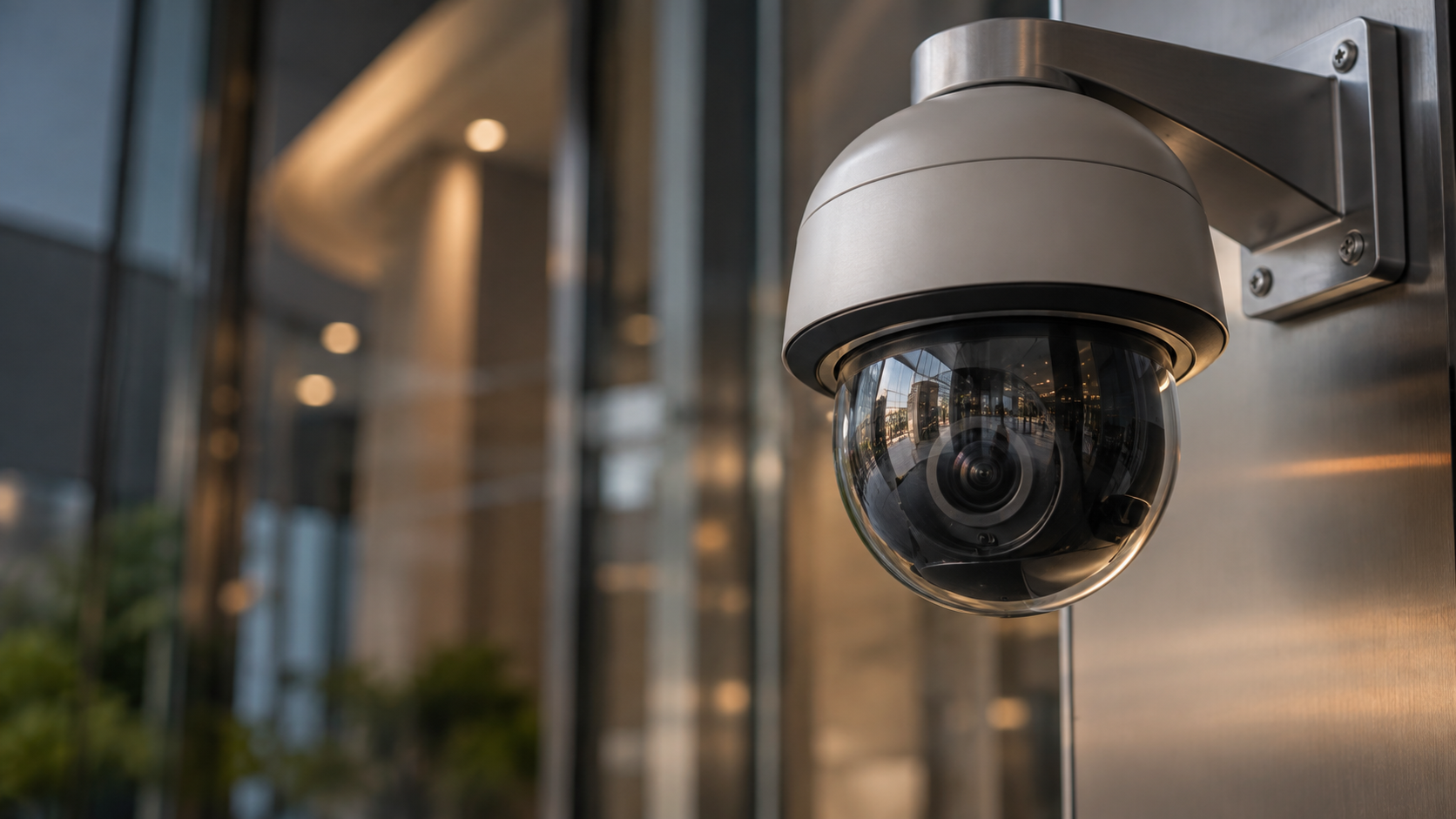
A CCTV design should not begin with a camera schedule.
It should begin with a question:
What must we be able to see, at exactly what location, and what must the recorded image allow us to do afterwards?
From there, the designer works backwards.
The required security outcome determines the target area. The target area influences the camera position. Camera position and distance determine the required field of view and lens. Lighting affects whether the theoretical image quality can actually be achieved. Recording settings then determine how much of that image quality survives into the stored footage, and those settings ultimately determine the network and storage requirements.
This is the difference between:
placing cameras on a floor plan
and
engineering a surveillance system.
The Singapore Police Force VSS Standard provides the baseline framework. It expects cameras to meet defined coverage requirements, calls for at least HD 1080p resolution and true WDR, and says required camera views should remain clear and unobstructed.
But the Standard does not design the project for us.
That still requires engineering.
This guide focuses on that engineering process rather than repeating the VSS FAQs already covered elsewhere in PATH Insights.
- Start with the surveillance objective, not the camera
Before selecting:
- camera manufacturer;
- megapixel count;
- lens;
- mounting point; or
- recorder,
define the surveillance objective.
For example:
“Provide a frontal image of every person entering through the main staff entrance.”
That is significantly more useful than:
“Install one dome camera at the entrance.”
The first statement tells the designer what must be achieved.
The second merely describes equipment.
Similarly:
“Monitor activity throughout the warehouse.”
is a different requirement from:
“Capture the registration plate of every vehicle entering the loading yard.”
Both may involve CCTV, but the engineering is completely different.
A practical CCTV design therefore begins with three things:
Design Question | Example |
|---|---|
What must be observed? | Person entering office |
Where must the useful image occur? | Entrance threshold |
What must the image achieve? | Identification-quality frontal image |
Once the required surveillance level has already been established, the designer can begin working out how to achieve it.
We have covered the SPF Detect, Observe, Recognise and Identify framework separately. The purpose here is not to re-explain those categories, but to show what happens after the required level has been selected.
- Turn the floor plan into target zones
A common mistake is to cover the floor plan with camera cones until there appear to be no blank spaces.
That proves only that the camera can theoretically see the area.
It does not prove that the camera provides the required detail.
A better approach is to identify target zones first.
For example, at a main entrance there may be two different requirements:
Lobby overview zone
Understand movement and activity.
Entrance identification zone
Obtain a useful frontal image as each person enters.
These may be achieved by one camera.
They may also require two.
The decision should come from the geometry, not from an arbitrary preference for fewer cameras.
Example
Imagine a wide corporate reception.
One ceiling-mounted camera gives a beautiful panoramic view of:
the reception desk, waiting area and entrance.
But a person entering occupies only a small percentage of the image.
The camera may therefore provide excellent situational awareness while providing poor identification.
The solution might be:
Camera 1 – wide lobby overview
and
Camera 2 – tighter frontal entrance view
The second camera is not redundant.
It is performing a different surveillance function.
- Understand field-of-view geometry
The physical width captured by a camera depends mainly on:
camera-to-target distance
and
field-of-view angle.
For a simplified horizontal field of view:
Scene Width=2×Distance×tan HFOV2
where:
HFOV = horizontal field-of-view angle.
This simple equation already explains why camera design changes dramatically with lens angle.
Assume the target is 5 metres from the camera.
Horizontal FOV | Approximate Scene Width at 5 m |
|---|---|
90° | 10.0 m |
60° | 5.77 m |
40° | 3.64 m |
The 90° camera sees nearly three times as much width as the 40° camera.
That sounds better until we consider image detail.
The same available pixels are now distributed across a much wider physical scene.
- Why a wider camera view can mean less useful detail
Assume, simply for illustration, a 1920-pixel-wide image.
At a 10-metre scene width:
1920/10=192 pixels per metre
At a 3.64-metre scene width:
1920/3.64≈527 pixels per metre
So the narrower field places significantly more of the available image resolution onto each metre of the scene.
This does not mean 527 pixels per metre is a universal SPF requirement.
It is simply an engineering illustration of an important principle:
The wider the field of view, the less image detail is available on a target of the same physical size and distance.
That is why:
“Use a wider lens so we can see more”
can sometimes make the surveillance design worse.
- Lens selection follows the required scene width
Once the designer knows:
target distance + required physical scene width
the approximate field of view can be determined.
The camera’s lens then needs to produce that view.
For a simple rectilinear lens:
HFOV=2×tan-1Sensor Width2×Focal Length
The precise field of view depends on:
camera sensor dimensions, lens design, aspect ratio and the manufacturer’s implementation.
This is why manufacturers normally provide:
camera design calculators
or
lens/FOV tables
for their products.
Practical design sequence
The designer should not say:
“Let’s use a 2.8 mm lens everywhere.”
Instead:
Required view → required width → distance → required field of view → suitable lens.
A 2.8 mm lens may be appropriate in one location and completely wrong in another.
- Camera mounting height is a security and image-quality decision
Mounting cameras higher makes them harder to reach.
But mounting them excessively high can create poor target angles.
This becomes particularly important for facial identification.
The SPF VSS Standard specifically says entrance cameras should be positioned looking towards rather than down at the doorway or driver.
Consider a simplified example.
Assume the centre of the face is approximately 1.65 m above floor level.
Camera A
Camera mounting height: 2.7 m
Horizontal target distance: 4 m
Height difference:
2.7-1.65=1.05m
Downward angle:
tan-11.05/4≈14.7°
Camera B
Camera mounting height: 5 m
Same target distance: 4 m
Height difference:
5-1.65=3.35m
Downward angle:
tan-13.35/4≈40°
Both cameras technically see the person.
But they see the person from very different angles.
Camera B may provide:
a very good view of the person’s head and shoulders
while providing a much poorer facial image.
The lesson is:
Camera height should be selected together with target distance and viewing angle, not independently.
- Design a specific identification point
For locations requiring a detailed facial image, it is useful to establish a defined capture zone.
For example:
1.5 metres inside the main entrance door
may be the position where every entrant naturally passes through the required image.
The designer then checks:
camera distance, target height, scene width, vertical angle, horizontal angle and lighting
at that specific location.
This is much stronger than saying:
“Camera covers entrance.”
Why target zones work
People may move throughout a lobby in many directions.
Trying to achieve Identification everywhere can require excessive camera numbers or extremely high resolution.
Instead, the design can deliberately create a point where the person is most likely to present a useful view.
Typical target locations include:
entrance doors, turnstiles, lift exits, reception counters and controlled pedestrian chokepoints.
- Horizontal angle matters too
Vertical angle is not the only concern.
A camera mounted far to the side of a doorway may see a person’s profile rather than a frontal image.
This can happen when cameras are positioned according to:
available ceiling space
rather than
the required target direction.
Consider the path of travel.
If people normally walk north through a doorway, the identification camera should ideally obtain a useful view of the direction from which their face will be presented.
A camera mounted at an extreme side angle may still produce a technically sharp image, but the wrong part of the person is being captured.
- Camera placement has to consider human behaviour
Good CCTV engineering is not purely geometry.
The designer should ask:
Where do people naturally walk?
Where will they turn their heads?
Where do queues form?
Could one person obscure another?
Will people carry umbrellas?
Are they likely to wear caps or helmets?
Will doors swing into the camera view?
Will future signage obstruct the scene?
The VSS Standard requires relevant camera fields of view to remain clear and unobstructed.
But that needs to be considered operationally, not just on the construction drawing.
A camera view that is perfect in an empty BIM model may become poor once the building is occupied.
- Designing with crowd density
Crowding is particularly relevant at:
lobbies, turnstiles, lift banks, event entrances and transport interfaces.
A camera may achieve the correct target detail when one person walks through the area.
But if ten people enter simultaneously, the rear subjects may be completely obscured.
That may require:
- multiple camera angles;
- staggered views;
- narrower chokepoints; or
- additional target cameras.
This is another reason CCTV design cannot be reduced to counting camera cones.
- Lighting should be designed with the camera
A theoretically perfect camera position can fail because of lighting.
Typical problems include:
bright windows behind the subject, direct sunlight, reflections from glass, vehicle headlights, dark exterior areas, glossy surfaces and uneven lighting.
The SPF VSS Standard calls for true WDR as part of the baseline camera requirement.
But WDR is not a substitute for good lighting design.
A camera can compensate only so far.
Engineering approach
For important capture points, consider:
daytime condition
night-time condition
emergency lighting condition
backlighting
light direction
reflections
and
subject movement
The camera should be tested under the conditions in which the building actually operates.
- IR is useful, but should not become the lighting strategy
Built-in infrared can help a camera produce usable images in low-light conditions.
But IR has limitations.
Colour information may be lost, reflective materials can behave unexpectedly and nearby surfaces can produce excessive IR reflection.
A good design therefore asks:
Can the environment itself be illuminated properly?
before simply specifying stronger infrared illumination.
The objective remains a usable image, not the highest quoted IR range on the datasheet.
- Camera resolution must be considered together with scene width
Higher resolution can provide more available image detail.
But resolution alone is not enough.
A high-resolution camera pointed at an excessively wide area may still provide poor target detail.
Conversely, a lower-resolution camera with a well-controlled field of view may provide excellent results at a defined target location.
This is why the workflow should remain:
Required target → required scene width → position → lens → resolution
rather than:
Buy highest megapixel camera → decide where to point it.
- Do not design from maximum datasheet resolution alone
A camera might advertise:
8MP
but the complete system may record at another resolution.
The useful chain is:
camera capture → encoding → network transmission → recording → playback
The lowest effective quality in that chain can limit the final evidential result.
For this reason, commissioning needs to evaluate the recorded image, not only the live camera view.
The VSS Standard specifically requires agreed monitor and recorded image quality to be documented at commissioning.
- Frame rate is an engineering parameter, not a quality badge
Increasing frame rate increases the number of moments captured every second.
But it also increases:
bandwidth and storage.
The correct frame rate depends on:
the speed of activity being captured and the amount of temporal detail required.
We have covered the SPF frame-rate recommendations separately.
For engineering purposes, the important point is:
Do not automatically configure every camera to the highest FPS supported by the device.
If the operational requirement can be achieved efficiently at a lower rate, unnecessary frame rate consumes storage without necessarily producing a meaningful security benefit.
Conversely, fast activity may justify more frames.
- Bitrate links image quality to network and storage design
Modern IP CCTV is commonly engineered using bitrate.
If a camera produces an average stream of:
3 Mbps
then approximately 3 megabits of data need to be transmitted every second.
The same value also drives storage consumption.
A useful basic relationship is:
Storage=Bitrate×Time
After converting bits into bytes:
GB/day≈Mbps×864008×1000
A useful simplified approximation is:
1Mbps≈10.8GB/day
So:
3 Mbps ≈ 32.4 GB/day
per continuously recorded camera.
- Worked CCTV storage example
Assume:
32 cameras
Average recording bitrate: 3 Mbps per camera
Continuous recording: 24 hours
Retention: 31 days
Per camera
3Mbps≈32.4GB/day
For 31 days:
32.4×31=1,004.4GB
Approximately:
1.0 TB per camera
32 cameras
1.0044TB×32=32.14TB
So the base video requirement is approximately:
32.1 TB
before considering:
RAID, system overhead, reserve capacity or growth.
The SPF VSS Standard separately calls for continuous recording, 31 days or more of storage, at least 20% reserve recording media and minimum RAID 5 support.
Those requirements therefore need to be layered onto the base recording calculation.
- Bitrate should not be guessed from megapixels
Two cameras with the same resolution may generate very different bitrates.
Bitrate can vary because of:
- codec;
- frame rate;
- scene complexity;
- movement;
- noise;
- quality setting;
- GOP structure;
- variable vs constant bitrate; and
- camera implementation.
A quiet office corridor may compress much more efficiently than:
a busy tree-lined external scene in heavy rain.
For preliminary design, manufacturer calculators and reasonable engineering assumptions can be used.
For final validation, the actual intended camera configuration is more meaningful.
- Do not size storage using only the nominal disk total
Suppose an NVR contains:
12 × 8 TB drives
The raw physical total is:
12×8=96TB
That does not mean:
96 TB of usable CCTV recording capacity.
With RAID, part of that physical capacity is used to provide resilience.
Formatting, filesystem and vendor overhead may reduce usable capacity further.
The correct comparison is therefore:
required video storage vs usable storage after the selected RAID/storage architecture
not:
required video storage vs number printed on the hard-drive cartons.
- RAID should be designed for resilience, not just capacity
The VSS Standard specifies minimum RAID 5 support.
That establishes a baseline.
For larger modern systems, however, the engineering team may need to consider whether:
RAID 5, RAID 6, distributed storage or another supported architecture
is more appropriate for the specific recorder and risk.
That is an engineering and vendor-architecture decision.
The important principle is:
Loss of one storage device should not automatically mean loss of the surveillance record.
- The 20% storage reserve needs to be shown clearly
The VSS Standard says at least 20% reserve recording media should be allowed.
The project calculation should therefore make that allowance visible rather than burying it inside an unexplained total.
For example:
Storage Component | Capacity |
|---|---|
Base required recording | 32.1 TB |
RAID impact | According to architecture |
Recording reserve | ≥20% allowance |
Final usable requirement | Engineering result |
Selected storage | Equal to or greater than requirement |
The Standard does not provide a detailed calculation convention for exactly how every storage vendor must implement that 20% reserve.
The important thing is to document the design basis transparently.
- Recording settings and storage cannot be designed separately
If the integrator later changes:
bitrate
from 2 Mbps to 5 Mbps,
the storage calculation changes.
If the client changes:
retention
from 31 to 90 days,
the storage calculation changes.
If cameras increase from:
50 to 70,
the storage calculation changes.
If FPS increases substantially:
the storage requirement may change.
So the camera configuration and storage design should be treated as one engineering package.
A storage calculation made before the final camera settings are known is only an estimate.
- CCTV also creates a network load
The detailed network engineering belongs in our next infrastructure guide, but CCTV designers still need to understand the relationship.
If 32 cameras each produce an average 3 Mbps stream:
32×3=96Mbps
That represents approximately:
96 Mbps of continuous recording traffic
before considering:
live viewing, playback, analytics, overhead and other services.
A 100 Mbps uplink would therefore obviously be inappropriate.
A 1 Gbps uplink may have substantial capacity in this example, but the actual network still needs to account for:
traffic distribution, redundancy, multicast/unicast behaviour where relevant and other connected services.
- Design the failure behaviour
CCTV engineering should also ask:
What happens when something fails?
Examples include:
Camera failure
Does the operator receive an alarm?
Switch failure
How many cameras disappear simultaneously?
Fibre/uplink failure
Is an entire floor lost?
Recorder failure
Is recording still available elsewhere?
Network failure
Can cameras continue recording locally?
Power failure
Do the cameras, PoE switches, recorder and viewing workstation remain operational?
The full resilience architecture will be covered in the PATH security infrastructure engineering guide.
But these questions need to influence the CCTV topology from the beginning.
- Avoid creating large failure domains
Imagine 96 cameras connected through one critical network device.
The design may work perfectly when everything is healthy.
But one device failure could potentially remove all 96 cameras.
An alternative architecture may divide the system across:
separate switches, network paths or recording resources
so a single failure affects a smaller portion of the system.
This is the idea of a failure domain.
Good system design asks:
What is the maximum surveillance capability we could lose from one fault?
not only:
How many ports can this switch support?
- Camera quantity should be the outcome, not the starting point
The objective should not be:
“Use the minimum possible number of cameras.”
Nor should it be:
“Install as many cameras as possible.”
The correct number is the number required to achieve the Operational Requirements efficiently.
One well-positioned camera may replace several poorly positioned cameras.
But equally, forcing one camera to perform several conflicting functions may compromise the entire design.
Camera quantity therefore emerges from:
requirements + geometry + obstruction + target detail + resilience
rather than a predetermined ratio based on floor area.
- Worked example: corporate office main entrance
Consider a corporate office entrance.
The requirements are:
- General lobby awareness
and
- Frontal identification of entrants.
The entrance opening is approximately 3 metres wide.
The camera can be positioned approximately 4 metres from the target zone.
Option 1: one very wide camera
Assume the camera is configured with approximately 100° horizontal FOV.
At 4 metres:
Scene Width=2×4×tan50°
Approximately:
9.5 metres
The camera sees:
the entrance, reception desk and much of the lobby.
Excellent overview.
But the 3-metre entrance occupies only part of that image width.
Option 2: targeted entrance camera
Assume a second camera is configured around 45° HFOV.
At 4 metres:
Scene Width=2×4×tan22.5°
Approximately:
3.3 metres
Now almost the entire horizontal image is concentrated on the entrance.
This camera can be engineered specifically around the target zone.
The wide camera gives:
context
The targeted camera gives:
detail
That is often a stronger design than expecting one wide camera to perform both functions.
- Now test the vertical geometry
Assume the targeted camera is mounted at approximately:
2.8 metres
and the person’s face is around:
1.65 metres
The height difference is:
2.8-1.65=1.15m
At a horizontal distance of 4 metres:
tan-11.15/4≈16°
This gives a relatively modest downward viewing angle.
The installer can then physically verify whether the face remains sufficiently frontal at the target point.
The calculation does not prove image quality by itself.
It helps the designer avoid obviously poor geometry before installation.
- Then test the real environment
Once installed, the entrance camera should be checked with a real person walking naturally through the target zone.
Test:
daytime
especially if bright external light is behind the person.
Test:
night
with the actual building lighting.
Check:
live image
and
recorded image.
Verify that the person occupies the expected part of the frame and that facial detail is usable.
If the result is poor:
adjust the lens, camera angle, mounting position, lighting or configuration.
This is engineering validation.
It should not be assumed that the CAD drawing proves the outcome.
- Commission against the design intent
The final commissioning record should allow somebody later to answer:
What was this camera supposed to do?
A good CCTV commissioning record can therefore capture:
Item | Example |
|---|---|
Camera ID | L01-CAM-ENT-01 |
Location | Main Staff Entrance |
Purpose | Entrant identification |
Target zone | 1–2 m inside doorway |
Camera type | Fixed |
Recorded resolution | As approved |
FPS | As design |
Approved FOV | Reference commissioning image |
Day test | Pass |
Night test | Pass |
Recorded-image test | Pass |
The SPF VSS Standard requires the agreed camera views and image quality for both monitor and recorded images to be properly documented and periodically reviewed.
The table above is simply one practical way of implementing that principle.
- Common engineering mistakes
Designing coverage instead of performance
A camera cone on a drawing proves visibility, not usable image detail.
Selecting cameras before defining target zones
This reverses the design process.
Using very wide lenses everywhere
Wide views increase coverage but reduce the amount of image devoted to each target.
Mounting every camera as high as possible
This may improve tamper resistance while harming facial viewing angles.
Treating megapixels as the design
Resolution is only one part of the imaging chain.
Ignoring lighting until commissioning
Lighting and camera performance need to be coordinated during design.
Using maximum camera resolution but recording lower-quality streams
The evidence comes from the recorded image.
Calculating storage from raw disk capacity
RAID and system overhead reduce usable capacity.
Treating bitrate as a fixed number for every camera
Real bitrate varies according to scene and configuration.
Adding cameras without recalculating storage
Retention can silently decrease even though the recorder remains healthy.
Backing up the NVR but not the network
If the PoE switch shuts down, the recorder may remain powered while the cameras disappear.
Accepting “camera online” as commissioning
Connectivity does not prove that the Operational Requirement has been achieved.
A Practical CCTV Engineering Workflow
The whole process can be summarised as:
Security requirement
↓
Target and target zone
↓
Required surveillance detail
↓
Camera position
↓
Horizontal and vertical geometry
↓
Scene width and lens
↓
Resolution and image quality
↓
Lighting
↓
Frame rate, codec and bitrate
↓
Network requirement
↓
Storage and resilience
↓
Installation
↓
Live and recorded verification
↓
Commissioning baseline
That is the difference between buying cameras and engineering a surveillance system.
Conclusion
CCTV engineering is not fundamentally about selecting the camera with the highest specification.
It is about controlling the complete imaging chain.
A good design starts with:
What must the system show?
Then determines:
where that image must be obtained
and engineers:
camera position → field of view → angle → lens → lighting → recording → storage → resilience
around that outcome.
The most important principle is simple:
Every camera should have a defined purpose, and the design should be able to demonstrate that the camera actually achieves that purpose.
A 4K camera looking at the wrong place from the wrong angle is still a poor security design.
A carefully positioned camera with the correct field of view, lighting, recording settings and storage architecture can provide far greater operational value.
For PATH, this engineering stage is also only part of the wider security lifecycle.
The system then needs to be:
installed correctly, integrated with the wider security environment, commissioned against the design intent, monitored, maintained and periodically reviewed.
That is where CCTV stops being a collection of devices and becomes part of a managed security system.
From Manpower to Managed Security. One operator, total accountability.
Company
Resources